The 'Au' keychain is essentially the first thing I successfully completed using 'household chemistry.' I was halfway through my first semester of general chemistry when I started working on it. It actually started with a conversation between my sister and I, during which she mentioned electroplating, and I started doing some research on it. I found directions on how to etch/plate a piece of metal, executed it (with minor adjustments) and then came up with an atomic-level theory based on what I saw happening. Needless to say, it was terribly flawed and underwent significant revision at the end of gen chem 2.
The final result you see here was achieved after multiple attempts. I had quite a few missteps along the way, some of which I will describe.
In all, I used table salt (NaCl), part of a computer casing (for the metal), a 9 volt battery, some wiring, electrical tape, a plastic container, and tap water.
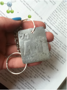
First I prepared the metal by cutting out the basic shape I wanted, ground it down, then sanded it until the edges were no longer sharp. Since I wanted to put a pattern on the front (the plan was to make a keychain after all), I had to come up with something to cover the parts I didn't want to etch away. First I tried taking an x-acto knife to electrical tape. That failed miserably. After several other failed attempts, I tried cutting large stickers down to the pattern I wanted. This worked surprisingly well. Upon later experimentation, I found that nail polish is non-conductive and a very effective way to get the pattern you want.
This piece (the one with the stickers) I attached to the anode end of the battery using the wire and electrical tape. I also cut out a sacrificial piece of metal which was connected to the cathode end the same way. Then I poured a bunch of salt into a plastic container and dissolved it with water, and placed the metal in the water.
This piece (the one with the stickers) I attached to the anode end of the battery using the wire and electrical tape. I also cut out a sacrificial piece of metal which was connected to the cathode end the same way. Then I poured a bunch of salt into a plastic container and dissolved it with water, and placed the metal in the water.
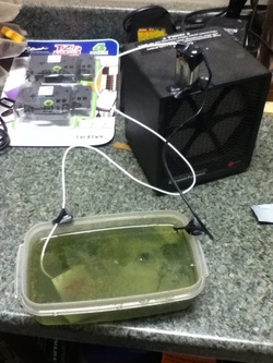
The water turned this awesome green color. Since most computer casings are made of steel (a metal alloy that is a combination of iron and carbon), I assume that the color is due to Fe2+ ions in solution. (I wondered for a bit whether it would be Fe3+ or Fe2+, but finally decided on Fe2+ because it is more likely to be green, and the oxidation/reduction potential favors Fe2+ anyway).
This was about the time at which I got frustrated with the speed at which the etching was proceeding. The battery was pretty unreliable and made the etching really slow. The connections kept sliding apart and the reaction would completely stop until I reconnected them. It was taking hours and hours. And I couldn't really walk away from the experiment, since the connections required seemingly constant supervision. So I decided to speed it up a bit.
I went into my box that houses broken electronics and retrieved an old charger for some long gone device. I cut the connection on the end off and (obviously) found the two electrodes... but they were both the same color wire, no distinguishing features. To figure out which end was the cathode and which end was the anode, I took two pieces of sacrificial metal and attached one to each end. As expected, one end bubbled much more than the other. The bubbles are associated with the reduction of hydrogen - the production of hydrogen gas. At this point, I did not know that; all I knew was that one end of the power source was gaining metal and the other end was losing it. I theorized that this was the negative end because the metal would positively charge itself (since metals usually form positive ions) in the presence of electricity (freely flowing electrons) and the positive ions would be drawn to the negative electrode. Not exactly accurate, but more on that later (below, "What happened"). I did figure out that the bubbles were occurring at the end that was not being etched.
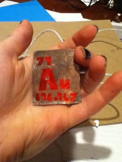
Anyway, when I attached the ends to the metal that I wanted to etch and plugged it in, it worked like a charm. Within 30 minutes, the etching was done. All I had to do after that was punch a hole for the jump ring, sand it, and wax it. For the hole, I used a hand drill gun with a small bit and drilled all the way through, then a larger one bit and drilled about a quarter of the way through on either side to make an indentation and make it look all fancy. Then I used a motor stone grinder and several grits of hand sandpaper to make it smooth and topped it off with some car wax.
This was about the time at which I got frustrated with the speed at which the etching was proceeding. The battery was pretty unreliable and made the etching really slow. The connections kept sliding apart and the reaction would completely stop until I reconnected them. It was taking hours and hours. And I couldn't really walk away from the experiment, since the connections required seemingly constant supervision. So I decided to speed it up a bit.
I went into my box that houses broken electronics and retrieved an old charger for some long gone device. I cut the connection on the end off and (obviously) found the two electrodes... but they were both the same color wire, no distinguishing features. To figure out which end was the cathode and which end was the anode, I took two pieces of sacrificial metal and attached one to each end. As expected, one end bubbled much more than the other. The bubbles are associated with the reduction of hydrogen - the production of hydrogen gas. At this point, I did not know that; all I knew was that one end of the power source was gaining metal and the other end was losing it. I theorized that this was the negative end because the metal would positively charge itself (since metals usually form positive ions) in the presence of electricity (freely flowing electrons) and the positive ions would be drawn to the negative electrode. Not exactly accurate, but more on that later (below, "What happened"). I did figure out that the bubbles were occurring at the end that was not being etched.
Anyway, when I attached the ends to the metal that I wanted to etch and plugged it in, it worked like a charm. Within 30 minutes, the etching was done. All I had to do after that was punch a hole for the jump ring, sand it, and wax it. For the hole, I used a hand drill gun with a small bit and drilled all the way through, then a larger one bit and drilled about a quarter of the way through on either side to make an indentation and make it look all fancy. Then I used a motor stone grinder and several grits of hand sandpaper to make it smooth and topped it off with some car wax.
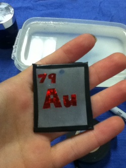
At one point I tried to copper plate the keychain (the stickers in the picture went on after I plated it). This worked beautifully. . . until I took the stickers off after etching. With the stickers came the copper. That was disappointing.
What happened - Chemistry
When I first started researching electroetching I was disappointed and frustrated at the lack of explanation provided with the instructions that I could find online. Most instructions supplied no explanation whatsoever, and those that did were sparse, unsatisfying, and unclear. Now, with a bit more chemistry under my belt, this is my best attempt at an explanation.
I essentially created a rudimentary galvanic (a/k/a, voltaic) cell. It is also quite similar to an electrolytic cell. There are components of each in my experiment, though as I am more familiar with a galvanic cell, I will attempt to explain what I know from that view point.
I essentially created a rudimentary galvanic (a/k/a, voltaic) cell. It is also quite similar to an electrolytic cell. There are components of each in my experiment, though as I am more familiar with a galvanic cell, I will attempt to explain what I know from that view point.
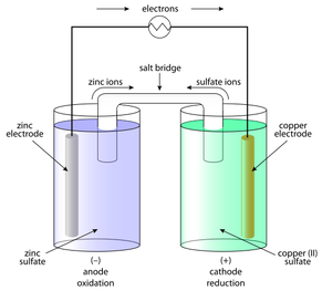
This picture illustrates a typical galvanic cell. Electrons flow from one electrode (piece of metal) to the other. This can be accomplished, as it is above, with the use of electricity (this is a classic component of an electrolytic cell: electrical energy is converted into chemical energy). When one piece of metal loses electrons it dissolves into solution as positive ions and when the other side gains electrons the metal picks up ions from the solution.
The first obvious difference between a galvanic cell and what I did is my lack of a salt bridge and the fact that used one container in place of two beakers. When I later learned about these reactions, I thought 'oh, I may not have used an actual bridge, but the salt I dumped in worked as one.' Not really. In a galvanic cell, the salt bridge serves the purpose of balancing charges. It lets cations and anions flow into the beakers in order to cancel out the charges caused from the metal ions forming and deforming. In my experiment, the salt acts, not to balance charges, but as an electrolyte to conduct electricity, since water is generally a poor conductor by itself (pure water does not conduct electricity at all, but the water we drink usually has trace amounts of ions in it, which makes it somewhat conductive. Swimming pools are so dangerous in lightning storms because they have tons of chlorine ions to conduct electricity.).
Another perceptible difference is the electrodes. While I had two electrodes, they were made of the same type of metal, rather than the two different types that you would typically see in a galvanic cell. This negates the need for two beakers. Since the identity of the ions that are getting removing from one electrode and added to the other is the same, you don't need to supply ions from another source (like a sulfate or nitrate solution, for example). The ions removed from one side will be the same ones that are picked up on the other.
Just as in a regular galvanic cell, I used two electrodes, and the typical anode=oxidation (loss of electrons) and cathode=reduction (gain of electrons) rule still applied to this reaction. The anode side loses electrons and mass (most of the mass is not lost as electrons but as metal ions), and the cathode side gains the lost electrons and mass. At the anode, the metal dissolves in the water/salt solution as positive cations. These cations are then picked up at the cathode, which now has negatively charged electrons hanging around (this is why a cathode is generally labeled with a positive sign and an anode with a negative sign - the electrons are attracted to the positive cathode and away from the negatively charged anode, though these signs are not indications of actual charges, which is essentially zero on the electrodes).
As I mentioned before, one side will bubble a lot. This is because of a side reaction with the water. The water is picking up electrons and bubbling out of solution as hydrogen gas. I found that this occurred at the end that was gaining mass - the cathode. The cathode is where reduction happens - there are a bunch of electrons around that can be picked up. And hydrogen likes to do just that. So, in theory at least, when this experiment is completed, your solution should be at least slightly basic, even though you started out with neutral water. Even if I had thought to, I did not have any way to test this at the time. I now plan to test this theory at some point, so I guess this experiment still has not reached completion.
 RSS Feed